The PCI specification provides for totally software driven initialization and configuration of each device (or target) on the PCI Bus via a separate Configuration Address Space. All PCI devices, except host bus bridges, are required to provide 256 bytes of configuration registers for this purpose.
Basically, the PCI Configuration Space is a set of registers. These registers are then mapped to memory locations such as the I/O Address Space of the CPU. The following content will explain the legacy way to acess and manipulate the configuration space. For the newer approach, the PCIe is used instead.
Two 32-bit I/O locations are used, the first location (0xCF8) is named CONFIG_ADDRESS, and the second (0xCFC) is called CONFIG_DATA.
-
CONFIG_ADDRESS (0xCF8) used to provide the configuration address to be accessed (configuration space selector)
-
CONFIG_DATA (0xCFC): used to transfer data to and from the CONFIG_DATA register.
The structure of the CONFIG_ADDRESS register is:

CONFIG_ADDRESS specifies the configuration address that is required to be accesses, while accesses to CONFIG_DATA will actually generate the configuration access and will transfer the data to or from the CONFIG_DATA register.
So say you wish to read the first register for the first device in the configuration, you would do something like:
outl(CONFIG_ADDRESS, 1 << 31);
uint32_t result = inl(CONFIG_DATA)
This is how to read a register from the PCI configuration space, now is necessary to know when we found a device (enumeration) . Basically if the first register is 0xFFFFFFFF, no device is connected to that bus at that device number. The brute force way is to scan all the buses and devices and then scan the functions if you find a device. More sophisticated ways will look at the header type of the first device on the first bus to determine which buses need to be checked.
Configuration Space Header:
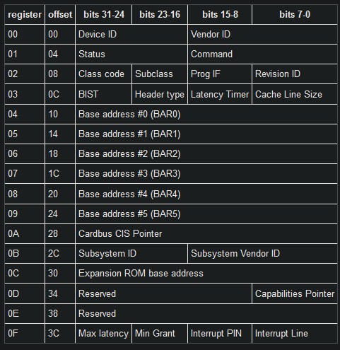
So in the previous example the first register contains both the device ID and vendor ID
All PCI compliant devices must support the Vendor ID, Device ID, Command and Status, Revision ID, Class Code and Header Type fields. Implementation of the other registers is optional, depending upon the devices functionality.
The Configuration Space Header provides information to enable the operating system to interact and control the device.
The legacy method was present in the original PCI, it is called Configuration Access Mechanism (CAM). For example, a software driver (firmware, OS kernel or kernel driver) can use these registers to configure a PCI device by writing the address of the device’s register into CONFIG_ADDRESS, and by putting the data that is supposed to be written to the device into CONFIG_DATA. Since this process requires a write to a register in order to write the device’s register, it is referred to as “indirection”.
The legacy method is still present for backwards compatibility.
RESOURCES:
https://doxygen.reactos.org/d0/df9/pcibus_8c.html
https://bsodtutorials.wordpress.com/2014/01/23/understanding-pci-configuration-space/
https://wiki.osdev.org/PCI#Header_Type_0x00
https://stackoverflow.com/questions/26808895/accessing-pci-space-through-toy-kernel