GDT and PROTECTED MODE:
- A GDT (Global Descriptor Table) é um mapa mantido pelo processador, que divide segmentos de memória. Quando um processo é alocado na memória e tenta acessar um endereço que não pertence ao bloco de memória que lhe foi atribuído, o processador, consultando a GDT (e verificando que aquele endereço está fora da região que foi destinada ao processo) dispara uma “interrupt” de “memory access violation” avisando o kernel.
- “Protected Mode” tem esse nome pq nele é possível dividir e controlar permissões de acesso a memória
IDT and PROTECED MODE:
- A IDT (Interrupt Descriptor Table) é um mapeamento das interrupções implementadas.
- Em “real mode” temos a IVT (interrupt vector table), que é substituída pela IDT quando passamos para “protected mode”.
- No real mode as interrupções (para executar funções e interagir com o hardware) são todas implementadas pela bios, mas passando para o protected mode perde-se acesso à bios, então, é necessário implementar todas as interrupções desejadas (from scratch! Painful…).
- No fim das contas, quem executa as funções do sistema é o kernel (lembre-se do “int 0x80”, por exemplo) e para chamar o sistema para executar coisas, carregamos os argumentos que vão ser utilizados e então chamamos a interrupção (passando o controle para o kernel, que executa o código resultado/correspondente a interrupção e depois devolve o controle para o processo).
- “Often, a (real-mode) operating system will want to redefine the way it responds to interrupts, rather than using the existing BIOS code. The CPU actually maintains a list of memory addresses where the interrupt routines live. Initially, these so-called interrupt vectors will all point to the memory occupied by the BIOS. Protected mode also has interrupts and from the perspective of a user program, they work the same way. You place some values in registers defined by the interrupt specification and call the interrupt”.
- “Now for a bit of good news. We don’t actually need to implement any interrupt handlers in our second-stage boot loader. We will need to reserve enough memory to hold 256 interrupts (which is 2,048 bytes) and fill it all with zeroes. Then we tell the CPU where this table is, because only then will it allow us to switch to protected mode. The real IDT will defined by our kernel – and from C code, so much nicer – once it’s running. In order to let the CPU know where the IDT is, we use an IDT pointer. This is the exact same structure we used for the GDT pointer”.
COMO FUNCIONA
- Definir a GDT
- Informar a CPU onde fica a GDT
- Definir a IDT
- Informar a CPU onde ficar a IDT
- Provisionar “interrupt handler code” para as interrupções da CPU
Address translation:
Usual Translation:
Logical address   -->   GDT -->  Linear address          --> Page tables --> Physical Address
(segment:offset)                 (segment base + offset)

\______________________________________________________/
                  Virtual address
             (can be either logical or linear)
If running in VMX non-root mode (i.e. in a VM) and EPT is enabled then:
Logical address   -->   GDT -->  Linear address          --> Page tables --> Guest Physical Address --> EPT --> (System) Physical Address
(segment:offset)                 (segment base + offset)

\______________________________________________________/                      \__________________________________________________________/
                  Virtual address                                                        Physical address
             (can be either logical or linear)
If an IOMMU is present (like the umbrella technology VT-d, dma and etc):
Logical address   -->   GDT -->  Linear address          --> Page tables --> Guest Physical Address --> EPT --> (System) Physical Address  -->  1 or 2 level translation --> (IO) Physical address
(segment:offset)                 (segment base + offset)

\______________________________________________________/                     \___________________________________________________________________________________________________________________/
                  Virtual address                                                        Physical address
             (can be either logical or linear)
Detailed Segmentation Unit Workflow (Address Translation):
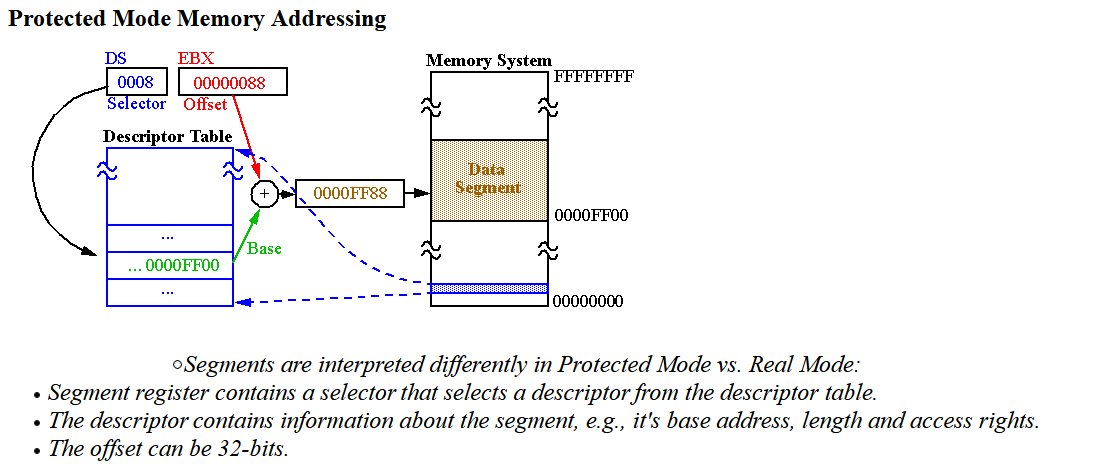
A logical address consists of a 16-bit segment selector (supplying 13+1 address bits) and a 16-bit offset. The segment selector must be located in one of the segment registers. That selector consists of a 2-bit Requested Privilege Level (RPL), a 1-bit Table Indicator (TI), and a 13-bit index. Whenever a program is loaded, the linking loader loads the “Segment Registers” with the appropriate selectors.
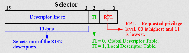
When attempting address translation of a given logical address, the processor reads the 64-bit segment descriptor structure from either the Global Descriptor Table (GDT) when TI=0 or the Local Descriptor Table (LDT) when TI=1. It then performs the privilege check:
where CPL is the current privilege level (found in the lower 2 bits of the CS register), RPL is the requested privilege level from the segment selector, and DPL is the descriptor privilege level of the segment (found in the descriptor). All privilege levels are integers in the range 0–3, where the lowest number corresponds to the highest privilege.
If the inequality is false, the processor generates a general protection (GP) fault. Otherwise, address translation continues. The processor then takes the 32-bit or 16-bit offset and compares it against the segment limit specified in the segment descriptor. If it is larger, a GP fault is generated. Otherwise, the processor adds the 24-bit segment base, specified in descriptor, to the offset, creating a linear physical address.
The privilege check is done only when the segment register is loaded, because segment descriptors are cached in hidden parts of the segment registers.
15                                                 3    2        0
+--------------------------------------------------+----+--------+
|          Index                                   | TI |   RPL  |
+--------------------------------------------------+----+--------+

TI = Table Indicator: 0 = GDT, 1 = LDT


<---- Selector ---->    +----- Segment Selector Register
+-------+----+-----+    v
| Index | TI | RPL | = DS
+-------+----+-----+            GDT                        LDT
   |      |             +---------------------+   +---------------------+
   |      +------------>| Null Descriptor     |   | Null Descriptor     |
   |                    +---------------------+   +---------------------+
   |                    | Descriptor 1        |   | Descriptor 1        |
   |                    +---------------------+   +---------------------+
   |                    |                     |   |                     |
   |                    ...     ...    ...   ...  ...     ...    ...   ...
   |                    |                     |
   |                    +---------------------+
   +------------------->| Descriptor K        |
                        +---------------------+
                        |                     |
                        ...     ...    ...   ...
In protected mode, code may always modify all segment registers except CS (the code segment selector). This is because the current privilege level (CPL) of the processor is stored in the lower 2 bits of the CS register. The only ways to raise the processor privilege level (and reload CS) are through the lcall (far call) and int (interrupt) instructions. Similarly, the only ways to lower the privilege level (and reload CS) are through lret (far return) and iret (interrupt return) instructions. In real mode, code may also modify the CS register by making a far jump (or using an undocumented POP CS instruction on the 8086 or 8088)[4]). Of course, in real mode, there are no privilege levels; all programs have absolute unchecked access to all of memory and all CPU instructions.
https://vivek-arora.com/?p=867