The VMCS region is a per logical processor data structure that’s also allocated and used by the processor for internal VMX operations. It also contains the settings used by the VMM to control guest operation. It does everything from manage transitions in and out of VMX operation (VM entries and VM exits) as well as processor behavior in VMX non-root operation.
A logical processor uses virtual-machine control data structures (VMCSs) while it is in VMX operation. These manage transitions into and out of VMX non-root operation (VM entries and VM exits) as well as processor behavior in VMX non-root operation. This structure is manipulated by the new instructions VMCLEAR, VMPTRLD, VMREAD, and VMWRITE.
- For a guest with multiple logical processors, the hypervisor can associate a different VMCS with each virtual processor. This is why the initialization required to allocate and initialize a VMCS region for each logical processor supported by the virtual machine.
- On a logical processor there can be numerous VMCS’s, but only one can be designated as active.
- The VMCS currently active on the logical processor is referred to as the current VMCS. Any modifications that are attempted to be made to a VMCS only operate on the current VMCS.
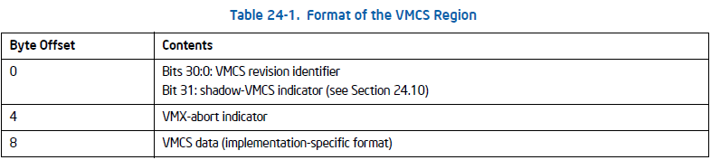
- The VMCS is a 4-KByte naturally aligned block of memory that holds the complete CPU state of both the host and the guest, including the segment registers, GDT, IDT, TR, various MSR’s, and control field structures for handling exit and entry operations.
he format of the VMCS:
struct __vmcs_t
{
  union
  {
    unsigned int all;
    struct
    {
      unsigned int revision_identifier : 31;
      unsigned int shadow_vmcs_indicator : 1;
    } bits;
  } header;
  unsigned int abort_indicator;
  char data[ 0x1000 - 2 * sizeof( unsigned ) ];
};
REGION INITIALIZATION:
int init_vmcs( struct __vcpu_t *vcpu, void *guest_rsp, void ( *guest_rip )( ), int is_pt_allowed )
{
  struct __vmcs_t *vmcs;
  union __vmx_basic_msr_t vmx_basic = { 0 };
  PHYSICAL_ADDRESS physical_max;
  vmx_basic.control = __readmsr( IA32_VMX_BASIC );
  physical_max.QuadPart = ~0ULL;
  vcpu->vmcs = MmAllocateContiguousMemory( PAGE_SIZE, physical_max );
  vcpu->vmcs_physical = MmGetPhysicalAddress( vcpu->vmcs ).QuadPart;
  RtlSecureZeroMemory( vcpu->vmcs, PAGE_SIZE );
  vmcs = vcpu->vmcs;
  vmcs->header.all = vmx_basic.bits.vmcs_revision_identifier;
  vmcs->header.bits.shadow_vmcs_indicator = 0;
  return TRUE;
}- Always use
RtlSecureZeroMemoryto zero out your allocations prior to use.
Create the control register adjustment function, that will query the IA32_FIXED MSRs to determine which bits can be set. Remember, this has to be done to ensure that an to enter VMX operation doesn’t fail because of unsupported bits in CR4 and CR0. The MSR’s are queried and then some bitwise operations are performed to check that the control register values are within an appropriate range and don’t set any bits outside of the reserved settings
union __cr_fixed_t
{
    struct
  {
        unsigned long low;
        long high;
    } split;
    struct
  {
        unsigned long low;
        long high;
    } u;
    long long all;
};

void adjust_control_registers( void )
{
  union __cr4_t cr4 = { 0 };
  union __cr0_t cr0 = { 0 };
  union __cr_fixed_t cr_fixed;
  cr_fixed.all = __readmsr( IA32_VMX_CR0_FIXED0 );
  cr0.control = __readcr0( );
  cr0.control |= cr_fixed.split.low;
  cr_fixed.all = __readmsr( IA32_VMX_CR0_FIXED1 );
  cr0.control &= cr_fixed.split.low;
  __writecr0( cr0.control );
  cr_fixed.all = __readmsr( IA32_VMX_CR4_FIXED0 );
  cr4.control = __readcr4( );
  cr4.control |= cr_fixed.split.low;
  cr_fixed.all = __readmsr( IA32_VMX_CR4_FIXED1 );
  cr4.control &= cr_fixed.split.low;
  __writecr4( cr4.control );
}
VMCS OPERATORS
Instructions that manipulate the VMCS:
vmclear
- This instruction is used primarily to copy VMX implementation specific data to the VMCS provided in the memory operand (i.e. the VMCS region provided for the logical processor.) The memory operand for vmclear is the physical address of the VMCS region, and following the execution of vmclear the VMCS is no longer active/current on the logical processor.
vmptrld
- The operand for vmptrld is the physical address of the VMCS. Once this instruction is execute the VMCS becomes both active and current on the current logical processor.
- This should only be executed once per logical processor as a logical processor can only have one active VMCS.
- There is such a thing called migrating a VMCS, however, that would require a vmclear to make the current VMCS on the logical processor inactive, and load all VMCS data into memory; and then execute vmptrld on the new logical processor.
vmread
- This instruction reads a component from a VMCS and stores it in a register / memory operand.
- The component that is read is based on the encoding of the field for the operand.
- There are three possible scenarios:
- If this instruction is executed in VMX root operation it will read data from the current VMCS
- if executed in non-root operation it will read from the VMCS referenced in the VMCS link pointer field in the current VMCS.
- If the link pointer is invalid, it will trap into the hypervisor and execute the proper exit handler for this instruction.
vmwrite
- This instruction writes the contents of a register / memory operand to the provided VMCS component.
- There are three possible scenarios:
- In VMX root operation, the instruction writes to the current VMCS.
- If operating in a non-root context his instruction will write to the VMCS referenced in the link pointer of the current VMCS
- if there is no link pointer it will trap into the hypervisor and execute the appropriate VM exit handler.
You cannot read/write directly from the VMCS region to get information about the virtualization state, only read and write through the use of vmread, and vmwrite.
Each of these instructions has error status codes associated.
VMCS Component Encoding
An encoding for the VMCS is a 32-bit field that every VMCS contains. This encoding value is provided in a register/memory operand to vmread or vmwrite. If you encode a field to be larger than 32-bits the instructions to read and write VMCS components will fail.
The structure of the 32-bit VMCS component encodings:
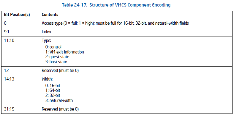
Access Type Enumeration:
enum __vmcs_access_e
{
    full = 0,
    high = 1
};- A value of 0 indicates full field access. All 64-bit fields must have this bit cleared (zeroed), this means that a vmread or vmwrite to a component with an encoding that uses the full access type accesses the entire field.
- As an example, if a 64-bit field uses the field access type high then a vmread or vmwrite to this encoded component will access the high 32-bits of the field.
Field Type Enumeration:
enum __vmcs_type_e
{
    control = 0,
    vmexit,
    guest,
    host
};
The field type distinguishes between the various types of VMCS fields.
- Control field types are types for components that control VMX rootand non-root operation, and encode components that control what operations in the guest cause VM-exits as well as various VMM settings.
- VM-exit field types are used for components that are used within the VM-exit handler, or occasionally used to read errors that occurred when executing a VMX instruction (recall, the read-only instruction error component).
- Guest field types are pretty self-explanatory, they’re used when encoding components that are required for guest state area initialization and proper guest operation. This goes for host field types as well.
Field Width Enumeration:
enum __vmcs_width_e
{
    word = 0,
    quadword,
    doubleword,
    natural
};
#define VMCS_ENCODE_COMPONENT( access, type, width, index ) ( unsigned )( ( unsigned short )( access ) | \
( ( unsigned short )( index ) << 1 ) | \
( ( unsigned short )( type ) << 10 ) | \
( ( unsigned short )( width ) << 13 ) )#define VMCS_ENCODE_COMPONENT_FULL( type, width, index ) VMCS_ENCODE_COMPONENT( full, type, width, index )#define VMCS_ENCODE_COMPONENT_FULL_16( type, index ) VMCS_ENCODE_COMPONENT_FULL( type, word, index )
#define VMCS_ENCODE_COMPONENT_FULL_32( type, index ) VMCS_ENCODE_COMPONENT_FULL( type, doubleword, index )
#define VMCS_ENCODE_COMPONENT_FULL_64( type, index ) VMCS_ENCODE_COMPONENT_FULL( type, quadword, index )Now that we have our enumerative types defined we can create our component encoding macros and create our VMCS field enumeration that contains all the encoded components for the VMCS.
These are the components that the guest register state is composed of:
GUEST_CR0 = VMCS_ENCODE_COMPONENT_FULL( guest, natural, 0 ),
GUEST_CR3 = VMCS_ENCODE_COMPONENT_FULL( guest, natural, 1 ),
GUEST_CR4 = VMCS_ENCODE_COMPONENT_FULL( guest, natural, 2 ),
GUEST_ES_BASE = VMCS_ENCODE_COMPONENT_FULL( guest, natural, 3 ),
GUEST_CS_BASE = VMCS_ENCODE_COMPONENT_FULL( guest, natural, 4 ),
GUEST_SS_BASE = VMCS_ENCODE_COMPONENT_FULL( guest, natural, 5 ),
GUEST_DS_BASE = VMCS_ENCODE_COMPONENT_FULL( guest, natural, 6 ),
GUEST_FS_BASE = VMCS_ENCODE_COMPONENT_FULL( guest, natural, 7 ),
GUEST_GS_BASE = VMCS_ENCODE_COMPONENT_FULL( guest, natural, 8 ),
GUEST_LDTR_BASE = VMCS_ENCODE_COMPONENT_FULL( guest, natural, 9 ),
GUEST_TR_BASE = VMCS_ENCODE_COMPONENT_FULL( guest, natural, 10 ),
GUEST_GDTR_BASE = VMCS_ENCODE_COMPONENT_FULL( guest, natural, 11 ),
GUEST_IDTR_BASE = VMCS_ENCODE_COMPONENT_FULL( guest, natural, 12 ),
GUEST_DR7 = VMCS_ENCODE_COMPONENT_FULL( guest, natural, 13 ),
GUEST_RSP = VMCS_ENCODE_COMPONENT_FULL( guest, natural, 14 ),
GUEST_RIP = VMCS_ENCODE_COMPONENT_FULL( guest, natural, 15 ),
GUEST_RFLAGS = VMCS_ENCODE_COMPONENT_FULL( guest, natural, 16 ),
GUEST_SYSENTER_ESP = VMCS_ENCODE_COMPONENT_FULL( guest, natural, 18 ),
GUEST_SYSENTER_EIP = VMCS_ENCODE_COMPONENT_FULL( guest, natural, 19 ),
s you can see above we are able generate the proper encoding value with our macros for each of these fields. This is the process we will use for all of our guest register state components, while using to determine how the specification indexes these fields.
GUEST_VMCS_LINK_POINTER = VMCS_ENCODE_COMPONENT_FULL_64( guest, 0 ),
GUEST_DEBUG_CONTROL = VMCS_ENCODE_COMPONENT_FULL_64( guest, 1 ),
GUEST_PAT = VMCS_ENCODE_COMPONENT_FULL_64( guest, 2 ),
GUEST_EFER = VMCS_ENCODE_COMPONENT_FULL_64( guest, 3 ),
GUEST_PERF_GLOBAL_CONTROL = VMCS_ENCODE_COMPONENT_FULL_64( guest, 4 ),
GUEST_BNDCFGS = VMCS_ENCODE_COMPONENT_FULL_64( guest, 9 ),

// --------------------

GUEST_ES_LIMIT = VMCS_ENCODE_COMPONENT_FULL_32( guest, 0 ),
GUEST_CS_LIMIT = VMCS_ENCODE_COMPONENT_FULL_32( guest, 1 ),
GUEST_SS_LIMIT = VMCS_ENCODE_COMPONENT_FULL_32( guest, 2 ),
GUEST_DS_LIMIT = VMCS_ENCODE_COMPONENT_FULL_32( guest, 3 ),
GUEST_FS_LIMIT = VMCS_ENCODE_COMPONENT_FULL_32( guest, 4 ),
GUEST_GS_LIMIT = VMCS_ENCODE_COMPONENT_FULL_32( guest, 5 ),
GUEST_LDTR_LIMIT = VMCS_ENCODE_COMPONENT_FULL_32( guest, 6 ),
GUEST_TR_LIMIT = VMCS_ENCODE_COMPONENT_FULL_32( guest, 7 ),
GUEST_GDTR_LIMIT = VMCS_ENCODE_COMPONENT_FULL_32( guest, 8 ),
GUEST_IDTR_LIMIT = VMCS_ENCODE_COMPONENT_FULL_32( guest, 9 ),
GUEST_ES_ACCESS_RIGHTS = VMCS_ENCODE_COMPONENT_FULL_32( guest, 10 ),
GUEST_CS_ACCESS_RIGHTS = VMCS_ENCODE_COMPONENT_FULL_32( guest, 11 ),
GUEST_SS_ACCESS_RIGHTS = VMCS_ENCODE_COMPONENT_FULL_32( guest, 12 ),
GUEST_DS_ACCESS_RIGHTS = VMCS_ENCODE_COMPONENT_FULL_32( guest, 13 ),
GUEST_FS_ACCESS_RIGHTS = VMCS_ENCODE_COMPONENT_FULL_32( guest, 14 ),
GUEST_GS_ACCESS_RIGHTS = VMCS_ENCODE_COMPONENT_FULL_32( guest, 15 ),
GUEST_LDTR_ACCESS_RIGHTS = VMCS_ENCODE_COMPONENT_FULL_32( guest, 16 ),
GUEST_TR_ACCESS_RIGHTS = VMCS_ENCODE_COMPONENT_FULL_32( guest, 17 ),
GUEST_SMBASE = VMCS_ENCODE_COMPONENT_FULL_32( guest, 20 ),
GUEST_SYSENTER_CS = VMCS_ENCODE_COMPONENT_FULL_32( guest, 21 ),

// -------------------

GUEST_ES_SELECTOR = VMCS_ENCODE_COMPONENT_FULL_16( guest, 0 ),
GUEST_CS_SELECTOR = VMCS_ENCODE_COMPONENT_FULL_16( guest, 1 ),
GUEST_SS_SELECTOR = VMCS_ENCODE_COMPONENT_FULL_16( guest, 2 ),
GUEST_DS_SELECTOR = VMCS_ENCODE_COMPONENT_FULL_16( guest, 3 ),
GUEST_FS_SELECTOR = VMCS_ENCODE_COMPONENT_FULL_16( guest, 4 ),
GUEST_GS_SELECTOR = VMCS_ENCODE_COMPONENT_FULL_16( guest, 5 ),
GUEST_LDTR_SELECTOR = VMCS_ENCODE_COMPONENT_FULL_16( guest, 6 ),
GUEST_TR_SELECTOR = VMCS_ENCODE_COMPONENT_FULL_16( guest, 7 ),
The above is an example of component encoding for all the fields in the guest register state using the macros we defined above. The rest of the guest components, particularly the non-register guests state components, are detailed on Appendix B and Chapter 24 in Volume 3C.
ORGANIZATION OF VMCS DATA
The VMCS data are organized into six logical groups:
- Guest-state area. Processor state is saved into the guest-state area on VM exits and loaded from there on VM entries.
- Host-state area. Processor state is loaded from the host-state area on VM exits.
- VM-execution control fields. These fields control processor behavior in VMX non-root operation. They determine in part the causes of VM exits.
- VM-exit control fields. These fields control VM exits.
- VM-entry control fields. These fields control VM entries.
- VM-exit information fields. These fields receive information on VM exits and describe the cause and the nature of VM exits. On some processors, these fields are read-only.
The VM-execution control fields, the VM-exit control fields, and the VM-entry control fields are sometimes referred to collectively as VMX controls.